
When purchasing equipment for fertilizer pelletizing, understanding the details behind the Disc Pelletizer Diagram is crucial for making informed decisions. Whether you are involved in manufacturing fertilizers or other industrial granules, the design of the pelletizer and its components directly impacts the efficiency, quality, and cost-effectiveness of your production process. In this guide, we’ll break down the key components in a typical disc pelletizer diagram, especially for buyers interested in disk fertilizer granule makers and pan pelletizers.
Understanding the Disc Pelletizer Diagram
A Disc Pelletizer Diagram provides a visual representation of the machine’s components and their interactions during the pelletizing process. This diagram is essential for anyone seeking to understand how materials, such as powders or granules, are transformed into uniform pellets through rotational motion.
In a pan pelletizer, the diagram shows the circular or semi-circular pan where the raw material is fed. As the pan rotates, the granules are rolled and compacted, eventually forming pellets of a consistent size. The diagram helps users visualize the angle of the pan, the speed of rotation, and the material flow, all of which affect the final product quality.
Key Components of the Disc Pelletizer
- Rotating Disc/Pan
- At the heart of the pan pelletizer is the rotating disc, which is usually slightly inclined. This inclination allows for the optimal movement of materials. The Disc Pelletizer Diagram will often highlight the angle of inclination, as this determines how efficiently pellets are formed and the size distribution of the final product.
Feeding System
- The material enters the pelletizer through a controlled feeding system. This section of the diagram illustrates where the raw materials (often a combination of fine powders and binder) are added to the pan. An efficient feeding system ensures consistent material flow and reduces waste.
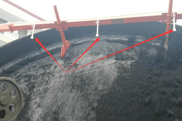
Spraying Nozzles
- Spraying water or binder is key to ensuring that the granules stick together. The disk fertilizer granule makers will detail the placement of these nozzles to maintain a constant supply of moisture and binder during the pelletizing process. This is especially important when producing fertilizer granule, where pellet integrity is essential.
Discharge System
- Once pellets have formed and reached the desired size, they are discharged from the pan. A well-designed discharge system, often featured in the diagram, ensures smooth removal without damaging the pellets. The discharge system can include chutes or conveyors, depending on the design.
Drive Mechanism
- The rotation of the pan is driven by a motor, and the Disc Pelletizer Diagram will show how the drive mechanism connects to the pan. The motor’s speed and torque control the pelletizing process’s intensity, which in turn affects the pellet's quality.
Conclusion
For equipment buyers, understanding the components in a Disc Pelletizer Diagram is vital for assessing the machine’s design and ensuring it meets production needs. Whether you are working with a disk fertilizer granule maker or a pan pelletizer, paying attention to the detailed diagram will help you identify key features that influence efficiency, pellet quality, and overall performance. Always take the time to review the diagram thoroughly before making your purchase to ensure that the pelletizer aligns with your production goals. There are more info on https://fertilizerequipmentmanufacturer.com/fertilizer-granulator-machine/disc-granulator-machine/